并联的电容对电压读数有什么影响?
硬件: CompactDAQ
|
|
||||||||||||||||||||||||||||||||||||||||||||||||||
问题: 在NI的很多板卡上,特别是cDAQ模块,使用并联的电容和电阻来增加输入阻抗。当测量多通道时会产生错误的读数。
解答:
板卡的内部电路如图所示。
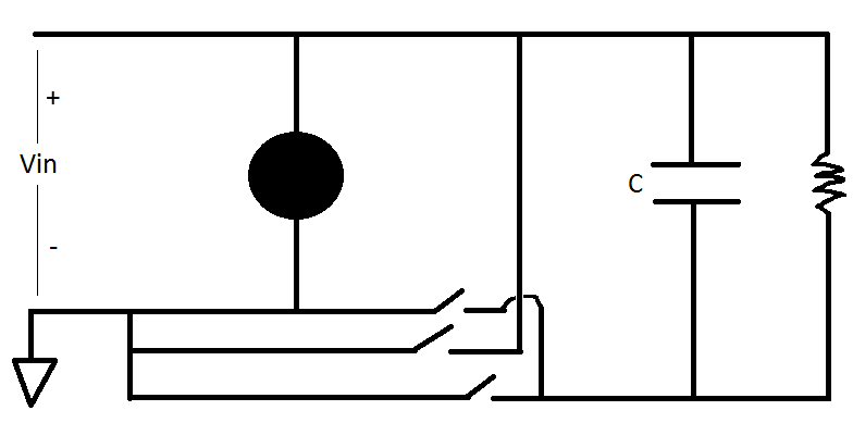
如果电压源阻抗较大,那么在较大电压范围内就不能正确测量多个通道,因为电压没有足够的时间来变化。式1表示电流(i),电容(C)和电压随时间的变化量(dV/dt)之间的关系。
i = C(dV/dt) (1)
使用欧姆定律(式2),可以得到电流,其中V是电压,i是电流,R是电阻。
V = iR (2)
将式2计算的电流代入式1,可以解出电压随时间的变化量(dV/dt)。
(V/R)/C = dV/dt (3)
该式可以用来计算在一定时间内的电压变化。乘以转换时间就可以得到通道间电压变化的最大值。
比如:
使用模拟输入模块NI-9205测量分压器的电压。通道配置为差分模式。使用通道0测量共模电压,通道1测量分压器的电压。Vin等于4.5V,电路如图所示。
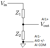
如果电路如图所示连接,我们不能得到正确的测量结果。测量结果与理论值的对比如表1所示。理论值为使用分压器电路的标准公式计算的。
| Resistances | Expected Voltage Readings | Actual Voltage Reading |
|---|---|---|
| Z1 = 750 KΩ Z2 = 75 KΩ |
AI0 = 0 V AI1 = 0.41 V |
AI0 = 0 V AI1 = 0.41 V |
| Z1 = 10 MΩ Z2 = 1 MΩ |
AI0 = 0 V AI1 = 0.41 V |
AI0 = 0 V AI1 = 0.15 – 0.20 V |
在高电阻值的情况下,通道1的测量是不准确的。使用式3和9205的说明手册可以解释该问题。9205手册的18页:9205的电容值为100pF,转换时间为4µs。代入式3:
(4.5 V/1X106)/100X10-12 = dV/dt = 45,000 V/s = 45 mV/µs
乘以转换时间4µs得到:
45 mV/µs x 4 µs = 180 mV = 0.18 V
意思是通道间的电压只能改变0.18V,那么通道1的实际电压读数就与理论值不同了。
解决这个问题可以通过减小分压电路的电阻,或者使用低电容值的模块。
相关链接: KnowledgeBase 3L8IETLO: How Do I Eliminate Ghosting From My Measurements?
KnowledgeBase 49F73C4G: What is the Difference Between Crosstalk and Ghosting?
附件:
|
|
||||||||||||||||||||||||||||||||||||||||||||||||||
报告日期: 05/02/2012
最近更新: 01/18/2013
文档编号: 5X1G35QQ