在NI Multisim PLD原理图中如何连接双向引脚
主要软件: Electronics Workbench>>Multisim
主要软件版本: 12.0.1
主要软件修正版本: N/A
次要软件: N/A
|
|
||||||||||||||||||||||||||||||||||||||||||||||||||
问题: 我正在创建Multisim PLD的原理图,并且我需要用双向引脚,我该如何连线才能读写FPGA呢?
解答:
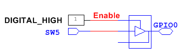
Multisim的PLD双向引脚包含三态端。当你向FPGA中写入数据时,需要将三态引脚设置为高电平;当你向FPGA读取数据时,需要将三态引脚设置为低电平。下图展示了如何设置双向引脚对FPGA的双向引脚对其进行读写操作。
向FPGA的GPIO0引脚写入:
向FPGA的GPIO2引脚读取:

相关链接: Developer Zone Tutorial: Program Xilinx PLD from the Multisim Environment
Developer Zone Tutorial: Teach Digital Concepts with the PLD Schematic in NI Multisim
附件:
|
|
||||||||||||||||||||||||||||||||||||||||||||||||||
报告日期: 07/18/2013
最近更新: 08/24/2015
文档编号: 6BH95NMC