SMU Best Practices: Understanding Compliance and Device Protection Errors
Overview
Source Measure Units (SMUs) can be powerful assets within an automated test system. However, in a complex system, there are caveats and behaviors that must be understood in order to avoid unwanted errors or costly downtime. To help reduce risk and maximize the uptime of your test system, this document presents common pitfalls and the best practices to follow during design and implementation. Additionally, the techniques discussed here will offer suggestions to minimize the effect to your system should you experience unexpected errors.
It should be noted that an implied recommendation is to always ensure that your system is utilizing the latest NI-DCPower device driver.
For more general recommendations for your PXI test systems, please refer to the Additional Resources section at the conclusion of this document.
Contents
- Device Protection
- General Recommendations
- Common Protection Conditions
- Handling Failures
- Additional Resources
Device Protection
NI SMUs contain robust protection circuitry and software to prevent damage to both the NI device and the device under test (DUT). If the module detects a condition which may become harmful, it is designed to respond accordingly. The device may enter protection regardless of which mode or output quadrant the SMU is operating in (i.e. DC Voltage or DC Current, Sourcing or Sinking). Situations should be avoided where the SMU may see a voltage or current spike large enough to trigger the protection mechanisms.
Compliance
Each SMU has a user programmable current and voltage limit that may be set for each output function. A current limit is set for voltage outputs, and a voltage limit is set for current outputs. A device will enter Compliance when, due to the load conditions, a channel cannot reach the requested output level because the programmed limit has been reached for either voltage or current. This state does not generate an error, but it may be queried through software. To avoid this state, ensure that limits are set appropriately according to the load conditions. Also, it is recommended to monitor the output of the device, using onboard measurements, to note any differences between the programmed and actual output. If the output is less than requested, this may indicate that a limit has been reached and the output is in Compliance. Since Compliance does not halt the operation of the device, much of this document will focus on understanding and preventing hardware protection errors.
Hardware Protection Errors
In addition to the user programmable limits, each device has internal, hardware-controlled limits which are actively monitored by the device circuitry. Exceeding theses limits will cause the SMU to halt the output of the device, generate a software error, and often change the color of a front panel LED to red. These limits are related to the design and capabilities of the specific device. After the device has engaged its protection circuitry, it must be reset in order to resume operation.
Common hardware errors that may be encountered are:
- Over Voltage Protection (OVP)
- Over Current Protection (OCP)
- Over Load Protection (OLP)
OVP is based on a hardware-controlled limit which disables the output of the SMU if a fault condition occurs that would cause the device to sink or source voltage beyond its capabilities (specifications). Some SMUs also have a feature that allows a user to set an additional hardware voltage limit to prevent damage to the connected DUT. This property monitors the Sense lines of the device to disable the output if the programmed limit is exceeded.
OCP, similarly, is based on a hardware-controlled limit which disables the output of the SMU if a fault condition occurs that would cause the device to sink or source current beyond its specifications.
OLP, similarly, is based on hardware-controlled limits which disables the output of the SMU if a fault condition occurs that would otherwise cause it to sink or source current or voltage beyond its specifications.
General Recommendations
- Protection errors are more likely to happen when operating at the maximum of a voltage or current range
- Protection errors can be triggered if there is an oscillation created when the SMU is connected to the
DUT- Avoid setting the output Current Level or Current Limit of the SMU at the maximum of the DUT’s output current
- Keep the SMU’s Voltage Limit as low as possible, especially when switching relays connected to the output or during changes that would cause the DUT’s impedance to fluctuate widely. This prevents the SMU’s output from floating to a significantly higher voltage as it tries to meet the requested current level at a higher impedance. This will lead to a spike of current when the DUT impedance once again decreases.
- Use the ‘Output Connected’ property set to False to disconnect the SMU output (as opposed to using the ‘Output Enabled’ property)
- Note: Setting the ‘Output Enabled’ property to FALSE configures the SMU with the following settings: Output Mode = DC Voltage, Voltage Level = 0V, Current Range: unchanged, Current Limit = 2% of Current range
- If connecting a DUT causes the device to exhibit symptoms of instability, such as unstable readings or excessive noise, the Transient Response property may need to be adjusted.
- ‘Slow’, ‘Normal’, ‘Fast’, and ‘Custom’ are the user selectable options for the Transient Response property. Slowing the response can reduce overshoot and lower the risk of saturation due to ringing; while increasing the response can help the SMU respond faster to load transitions. ‘Normal’ balances stability and the speed of the device. It is the default transient response setting and is appropriate for most situations.
- Tip: Refer to the NI DC Power Supplies and SMUs Help: Transient Response for more information about Transient Response settings.
- When using the SMU in ‘Force Current, Measure Voltage’ (FIMV) mode:
- Configure the SMU for the highest current range prior to calling ‘Initiate’
- Enable the output with the Current Level property set to 0uA. This allows the SMU to follow the
DUT’s voltage without interacting with it - Allow proper time for switching and DUT feedback loop settling before changing to the desired current level
- If higher accuracy is required, change the desired current range after settling
Common Protection Conditions
Below are listed some common conditions in which the protection circuitry of the modules may be triggered. Following the description of each is a recommended best practice to avoid the condition.
Hot Switching Channels
If an SMU is outputting a voltage and then a connection to another voltage is made, there is a likelihood of protection errors. This is often caused by one of the following conditions:
- While disconnected from the DUT, most commonly via a relay on the device interface board (DIB), the SMU is configured to source current. This will typically cause the channel to float to its positive or negative voltage limit. When then connected to the DUT or other resource, the change in voltage will cause a current spike which could cause a protection error.
- While disconnected from the DUT, most commonly via a relay on the DIB, the SMU is configured to source a voltage, or the output is disabled. When the SMU is then connected to the DUT or other resource, if there is a substantial voltage difference, a protection error is likely to result.
Best Practice
The SMU should always be connected to the DUT or DIB resource. If this is not possible (for example, if switching or external disconnect is required) ensure the SMU is always connected with a known voltage, ideally 0V, and the SMU is sourcing this voltage in its highest current range when connected.
High Load Variation
If the SMU is connected to a load that is suddenly, greatly increased, a protection error is likely to result. This generally occurs when the SMU channel is configured for a small current range (relative to the device’s capabilities), and the load requires a large instantaneous current.
Best Practice
When connected to a load with a large inrush current, use the highest current range of the SMU when enabling or turning ON the device. Once a steady state is reached, if needed for accuracy, change the SMU to a lower current range.
Voltage Compliance
When the SMU is configured to source current and continually reaches the voltage limit, a protection error is more likely to occur.
Best Practice
Ensure that proper limits are set for each test to avoid conditions which put the SMU into voltage compliance.
Combined Channels & Voltage Compliance
When reconfiguring merged channels, it is possible to have multiple channels connected and configured differently (for example, different modes, voltages, current, etc.). This generally increases the likelihood for reaching compliance and therefore causing protection errors.
Best Practice
Configure merged channels simultaneously by applying settings based on HW or SW triggers. This will increase repeatability and minimize the time that channels are configured differently. In addition, use different current/voltage limits for each channel so only one channel will go in/out of compliance at a time.
Floating Channels
Some SMUs (e.g. PXIe-4139) support channels being disconnected from the front connector of the instrument using the ‘Output Connected’ property. On other NI SMUs (e.g. PXIe-4143), the output is always connected. Channels that are unnecessarily connected have the potential to reach the voltage limit unintendedly which may cause a protection error.
Tip: Refer to the NI DC Power Supplies and SMUs Help: Supported Properties by Device to determine which devices support the ‘Output Connected’ Property.
Best Practice
If a channel needs to apply very little loading on the DUT, set the ‘Output Connected’ property to FALSE instead of sourcing 0A as this will let the output float instead of potentially railing at the voltage limit. If the SMU has a channel that cannot be disconnected, consider using an external relay to accomplish this.
Handling Failures
If a protection error occurs, the affected channel shuts down until it is reset. The easiest method to get the channel back into a working state is calling niDCPower Reset. This sets the device back to its default values and clears the error. Alternatively, calling niDCPower Reset Device, rebooting the system, or powering cycling the tester will clear the error.
Users can likewise integrate this reset directly into their program to reduce the impact of an error. As seen in Figure 1, the specific error can be polled, the SMU configuration exported, the device reset, then the SMU configuration imported again to return the unit to its previous mode of operation before the error occurred.
Note: The DCPower Import and Export feature is not supported when using Sequencing.
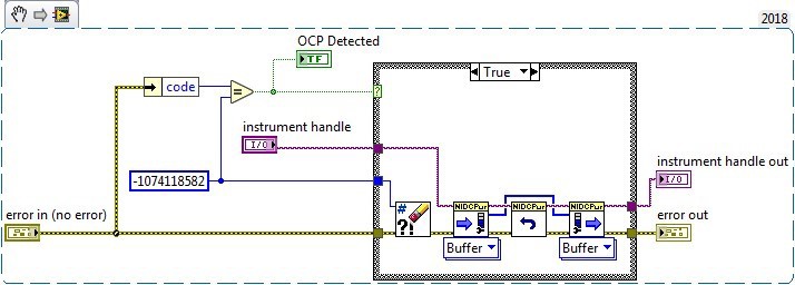
Figure 1: Example method of clearing an OCP error using DCPower Import and Export
When debugging protection errors, it is important to note that the error often occurs during a measurement or when calling niDCPower Initiate. This, however, is just indicative of when the error was read by software. The actual error could have happened much earlier. To determine when the error truly occurs, watch for the red light on the front panel on the SMU or call functions that force the software to interact with the hardware (for example, niDCPower Initiate, measure, etc.). It is also important to ensure that state of any supporting hardware (e.g. DIB relays) is properly configured after an error is cleared.