Measuring Vibration with Accelerometers
This resource provides information to help you understand basic vibration concepts, how accelerometers work, and how different sensor specifications impact accelerometer performance in your application. After you decide on your sensors, you can consider the required hardware and software to properly condition, acquire, and visualize microphone measurements. You can also consider any extra signal conditioning you may need for your sensors.
What is Vibration?

Vibration is the movement or mechanical oscillation about an equilibrium position of a machine or component. It can be periodic, such as the motion of a pendulum, or random, such as the movement of a tire on a gravel road. Vibration can be expressed in metric units (m/s2) or units of gravitational constant g, where 1 g = 9.81 m/s2. An object can vibrate in two ways: free vibration and forced vibration.
Free vibration occurs when an object or structure is displaced or impacted and then allowed to oscillate naturally. For example, when you strike a tuning fork, it rings and then the sound eventually diminishes. Natural frequency often refers to the frequency at which a structure “wants” to oscillate after an impact or displacement. Resonance is the tendency for a system to oscillate more violently at some frequencies than others. Forced vibration at or near an object’s natural frequency causes energy inside the structure to build. Over time, the vibration can become quite large even when the input forced vibration is very small. If a structure has natural frequencies that match normal environmental vibration, the structure vibrates more violently and prematurely fails.
Forced vibration occurs when a structure vibrates because an altering force is applied. Rotating or alternating motion can force an object to vibrate at unnatural frequencies. An example of this motion is imbalance in a washing machine, where the machine shakes at a frequency equal to the rotation of the turnstile. In condition monitoring, you can use vibration measurements to indicate the health of rotating machinery such as compressors, turbines, or pumps. These machines have a variety of parts, and each part contributes a unique vibration pattern or signature. By trending different vibration signatures over time, you can predict when a machine will fail and properly schedule maintenance for improved safety and reduced cost.
Measuring Vibration
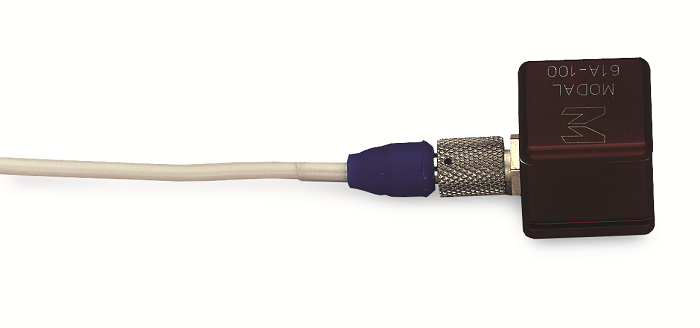
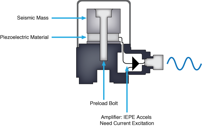
An accelerometer or ceramic piezoelectric sensor is commonly used to measure vibration. Most accelerometers rely on the use of the piezoelectric effect, which occurs when a voltage is generated across certain types of crystals as they are stressed. The acceleration of the test structure is transmitted to a seismic mass inside the accelerometer, whichgenerates a proportional force on the piezoelectric crystal. This external stress on the crystal then generates a high-impedance, electrical charge proportional to the applied force and, thus, proportional to the acceleration.
There are two common types of accelerometers: Piezoelectric (charge mode) accelerometers and Integrated Electronic Piezoelectric (IEPE) accelerometers.
Accelerometers are full-contact transducers typically mounted directly on high-frequency elements, such as rolling-element bearings, gearboxes, or spinning blades. These versatile sensors can also be used in shock measurements, such asexplosions and failure tests, and slower, low-frequency vibration measurements. The benefits of an accelerometer include linearity over a wide frequency range and a large dynamic range.
Charge mode accelerometers require an external amplifier or inline charge converter to amplify the generated charge, lower the output impedance for compatibility with measurement devices, and minimize susceptibility to external noise sources and crosstalk.
IEPE accelerometers have a charge-sensitive amplifier built inside them. This amplifier accepts a constant current source and varies its impedance with respect to a varying charge on the piezoelectric crystal. Measurement hardware made for these types of accelerometers provide built in current excitation for the amplifier. You can then measure this change in impedance as a change in voltage across the inputs of the accelerometer.
Another sensor you can use to measure vibration is the proximity probe. Unlike accelerometers, which measure acceleration to determine vibration, proximity probes are noncontacting transducers that measure distance to a target. These sensors are almost exclusively used in rotating machinery to measure the vibration of a shaft. An example of a common application is machine monitoring and protection measurements for mechanical systems like turbo machinery. Because of the flexible fluid film bearings and heavy housing, vibrations do not transmit well to the outer casing, so you use proximity probes instead of accelerometers to directly measure shaft motion.
Choosing the Right Accelerometer
Because accelerometers are so versatile, you can choose from a variety of designs, sizes, and ranges. Understanding the characteristics of the signal you expect to measure and any environmental constraints can help you sort through all the different electrical and physical specifications for accelerometers.
Vibration Amplitude
The maximum amplitude or range of the vibration you are measuring determines the sensor range that you can use. If you attempt to measure vibration outside the sensor range, it distorts or clips the response. Typically, you would use an accelerometers to monitor high vibration levels with a lower sensitivity and lower mass.
Sensitivity
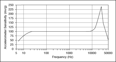
Sensitivity is one of the most important parameters for accelerometers. It describes the conversion between vibration and voltage at a reference frequency, such as 160 Hz. Sensitivity is specified in mV per G. If typical accelerometer sensitivity is 100 mV/G and you measure a 10 G signal, you expect a 1000 mV or 1 V output. The exact sensitivity is determined from calibration and usually listed in the calibration certificate shipped with the sensor. Sensitivity is also frequency dependent. A full calibration across the usable frequency range is required to determine how sensitivity varies with frequency. Figure 4 shows the typical frequency response characteristics of an accelerometer. In general, use a low-sensitivity accelerometer to measure high amplitude signals and a high-sensitivity accelerometer to measure low amplitude signals.
Number of Axes
You can choose from two axial types of accelerometers. The most common accelerometer measures acceleration along only a single axis. This type is often used to measure mechanical vibration levels. The second type is a triaxial accelerometer. This accelerometer can create a 3D vector of acceleration in the form of orthogonal components. Use this type when you need to determine the type of vibration, such as lateral, transverse, or rotational.
Weight
Accelerometers should weigh significantly less than the structure you are monitoring. Adding mass to the structure can alter its vibrational characteristics and potentially lead to inaccurate data and analysis. The weight of the accelerometer should generally be no greater than 10 percent of the weight of the test structure.
Mounting Options
Another consideration for your vibration measurement system is how to mount the accelerometer to the target surface. You can choose from four typical mounting methods:
- Handheld or probe tips
- Magnetic
- Adhesive
- Stud mount
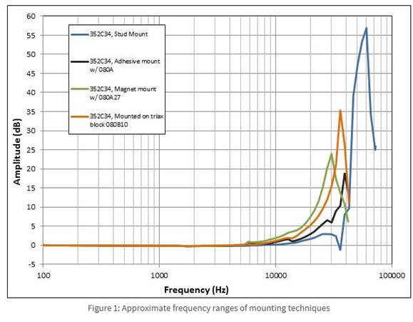
Stud mounting is by far the best mounting technique, but it requires you to drill into the target material and is generally reserved for permanent sensor installation. The other methods are meant for temporary attachment. The various attachment methods all affect the measurable frequency of the accelerometer. Generally speaking, the looser the connection, the lower the measurable frequency limit. The addition of any mass to the accelerometer, such as an adhesive or magnetic mounting base, lowers the resonant frequency, which may affect the accuracy and limits of the accelerometer’s usable frequency range. Consult accelerometer specifications to determine how different mounting methods affect the frequency measurement limits. Table 1 shows typical frequency limits for a 100 mV/G accelerometer.
| Method | Frequency Limit |
| Handheld | 500 Hz |
| Magnetic | 2000 Hz |
| Adhesive | 2500 to 5000 Hz |
| Stud | > 6000 Hz |
Table 1. Frequency Limits for Mounting a 100 mv/G Accelerometer.
Figure 5 shows the approximate frequency ranges of different mounting techniques, including stud mounts, adhesive mounts, magnet mounts, and triaxial block mounts.
Environmental Constraints
When choosing an accelerometer, note critical environmental parameters such as maximum operating temperature, exposure to harmful chemicals, and humidity. You can use most accelerometers in hazardous environments because of their rugged and reliable construction. For additional protection, industrial accelerometers built from stainless steel can protect the sensors from corrosion and chemicals.
Use a charge-mode accelerometer if the system must operate in extreme temperatures. Since these accelerometers do not contain built-in electronics, the operating temperature is limited only by the sensing element and materials used in the construction. However, since they do not have built-in conditioning and charge amplification, charge-mode accelerometers are sensitive to environmental interference and require low-noise cabling. If the environment is noisy, use an inline charge converter or IEPE sensor with a built-in charge amplifier.
Humidity specifications are defined by the type of seal on the accelerometer. Common seals include hermetic, epoxy, or environmental. Most of these seals can withstand high levels of moisture, but NI recommends a hermetic seal for fluid immersion and long exposure to excessive humidity.
Cost
Although charge mode and IEPE accelerometers have similar costs, IEPE accelerometers have a significantly lower cost for larger, multichannel systems because they do not require special low-noise cables and charge amplifiers. In addition, IEPE accelerometers are easier to use because they require less care, attention, and effort to operate and maintain.
Looking for a sensor?
NI offers Integrated Circuit-Piezoelectric, or ICP®, sensors from PCB. ICP® is a trademark of PCB Piezotronics, Inc., and it refers to the Integrated Electronic Piezoelectric (IEPE) acceleration and vibration sensors they manufacture. Sensors are available in general-purpose, industrial, triaxial, and impact hammer form factors.
Signal Conditioning for Accelerometers
When preparing an accelerometer to be measured properly by a DAQ device, you need to consider the following factors to ensure you meet all your signal conditioning requirements:
- Amplification to increase measurement resolution and improve signal-to-noise ratio
- Current excitation to power the charge amplifier in IEPE sensors
- AC coupling to remove DC offset, increase resolution, and take advantage of the full range of the input device
- Filtering to remove external, high-frequency noise
- Proper grounding to eliminate noise from current flow between different ground potentials
- Dynamic range to measure the full amplitude range of the accelerometer
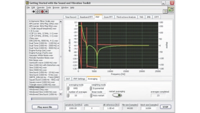
To learn more about how to condition, acquire, analyze, and display accelerometer measurements, download the Engineer's Guide to Accurate Sensor Measurements.
Connecting Accelerometers to NI Hardware
After you know your sensor or test needs, deciding on the hardware to collect that data is the next important step. The acquisition hardware quality determines the quality of the data you collect.
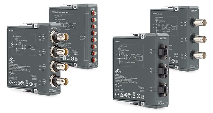
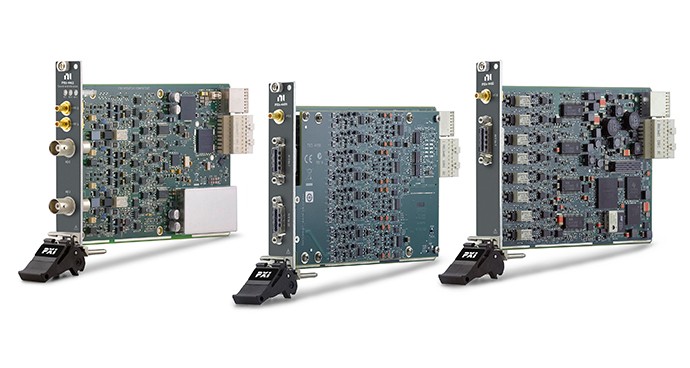
NI offers a range of sound and Vibration hardware that can acquire vibrational data and is compatible with a variety of IEPE sensors.
To help verify compatibility between an NI sound and vibration device and an IEPE sensor, accelerometers, and so on, refer to Excitation and Compliance Voltage for IEPE Sensors in NI Cards. If a preamplifier is used, NI sound and vibration hardware still works, but the signal characteristics may change. Verify the output of the preamplifier is within the sound and vibration hardware input range. Likewise, for non-IEPE sensors, ensure the sensor output is compliant with device input capabilities.
Simple Hardware Setup
Pair Your Accelerometer with Recommended Hardware
The CompactDAQ Sound and Vibration Bundle simplifies connecting your accelerometer or vibration sensor with a bundle of popular sound and vibration module(s) and a CompactDAQ chassis.
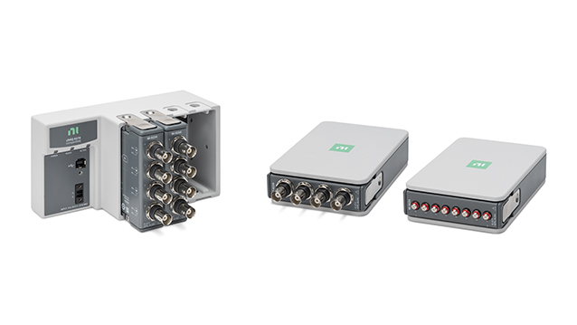
Other Products for Measuring Vibration
The following products interface with accelerometers to measure vibration signals. Use these products for audio test; machine condition monitoring; and noise, vibration, and harshness (NVH) applications. These products work for both sound and vibration measurements. Learn more about measuring sound with microphones to choose the right sensors and use with NI products.
References
- Lally, Jim. “ACCELEROMETER SELECTION CONSIDERATIONS, Charge and ICP® Integrated Circuit Piezoelectric.” PCB Group Inc. 2005. https://www.pcb.com/techsupport/docs/vib/TN_17_VIB-0805.pdf
- “Introduction to ICP® Accelerometers.” PCB Piezoelectronics. http://www.pcb.com/techsupport/tech_accel
- “Steps to selecting the right accelerometer.” Endevco. https://www.endevco.com/news/newsletters/2012_07/tp327.pdf