Isolation Types and Considerations when Taking a Measurement
Overview
Learn about isolation topologies used in instruments and the positive benefits that isolation can provide. Article topics include ground loops, common-mode voltage, isolation topologies, analog isolation, digital isolation, and isolation types.
Contents
- What Is Isolation?
- Isolation Topologies
- Analog Versus Digital Isolation
- Isolation Types
- Summary
- Next Steps
What Is Isolation?
Isolation is a method of physically and electrically separating two distinct parts of an instrument. When the term isolation is used with instruments, it most likely refers to electrical isolation, which means that current does not flow between the two parts of the system that are isolated from each other. There are several advantages of electrical isolation but one of the largest advantages, in regards to measurement accuracy, is that isolation breaks ground loops.
Isolation also uses the physical and electrical barriers to provide safety benefits by keeping high voltages or high transient voltages away from the user or away from important circuit components, which we will discuss in later sections.
First, here’s a quick review of ground loops, which are covered in more detail in the Grounding Considerations for Improved Measurements white paper in the Instrument Fundamental Series.
Ground Loops
Ground loops are the most common source of noise in acquisition applications. They occur when two connected terminals in a circuit are at different ground potentials, which causes current to flow between the two points. This potential difference causes error in the measured voltage, V_m, which can be calculated using Equation 1.
Equation 1: Measured Voltage With a Ground Loop Present.
Where:


The Grounding Considerations for Measurements white paper discusses how to eliminate ground loops by ensuring only one ground reference exists in the signal source and measurement system setup. However, using isolated hardware also removes ground loops, because it eliminates the path for current to flow between the ground of the signal source and the ground of the measurement system.
Isolation Topologies
In general, there are three different types of isolation topologies, from a low level of protection to a high level of protection, respectively:
- Channel-to-earth isolation
- Bank (channel-to-bus) isolation
- Channel-to-channel isolation
Channel-to-Earth Isolation
This is the lowest protection level of isolation for an instrument. See Figure 1 for a schematic of channel-to-earth isolation. The voltages present at AI 1, AI 2, and AI Ground are not isolated from each other; however, they are isolated from the instrument ground. This isolation topology breaks ground loops between AI 1 and the earth ground, but it is possible that a current present on AI 1 could induce a voltage on AI 2, because they are not isolated from each other.
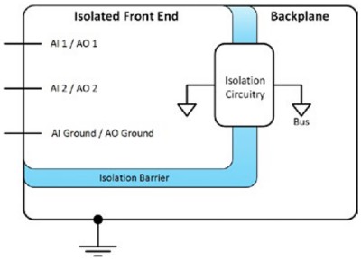
Figure 1: Channel-to-earth isolation does not isolate channels from each other but does isolate the channels from instrument ground.
Bank (Channel-to-Bus) Isolation
In bank isolation, also known as channel-to-bus isolation, several physical lines are built into groups called banks. See Figure 2 for this architecture. Because isolation barriers exist between channels in different banks, the ground loop protection is high between banks. However, it is still possible in this topology that signals on channels within a bank can affect each other.
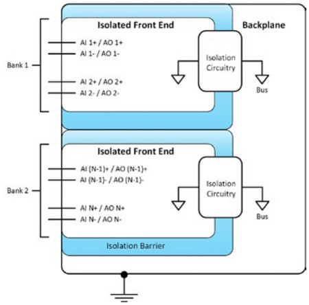
Figure 2: In bank isolation, the ground loop protection is high between different banks.
Channel-to-Channel Isolation
This topology provides the most comprehensive protection for the signals on the instrument lines because not only are all channels isolated from earth ground, but each channel is also isolated from all other individual channels. See this topology in Figure 3.
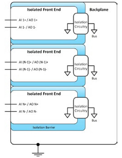
Figure 3: In channel-to-channel isolation, each channel is isolated from all other individual channels.
Analog Versus Digital Isolation
Analog input or output channels can be isolated using two different methods regardless of the instrument isolation topology. The difference between the two methods lies in the location of the isolation circuitry in the instrument. Analog isolation is where the isolation circuitry is in the path prior to the analog-to-digital convertor (ADC) and it acts on the analog signal. Digital isolation is where the isolation circuitry is after the ADC, because it acts on the newly digitized data.
Analog Isolation
An isolation amplifier is one of the more common parts used to provide isolation in the analog front end of an instrument. As shown in Figure 4, the analog data passes from the sensor into the I/O connector through the gain amplifier into the isolation amplifier and then to the ADC.

Figure 4: An isolation amplifier is one of the more common parts used to provide isolation in the analog front end of an instrument.
One large benefit of analog isolation is that it protects the ADC. Because the isolation is provided before the ADC, the ADC is less likely to be damaged by transient or high voltages. Analog isolation does, however, have disadvantages. First, because analog isolation is not perfect and it lies before the ADC, it can add gain, nonlinear, or offset error to the analog signal before it reaches the ADC. This is not ideal and can decrease the accuracy of the measurement. In addition, analog isolation components can introduce longer settling times and are often more expensive than their digital isolation counterparts.
Digital Isolation
As opposed to analog isolation, digital isolation circuitry is placed after the ADC in the instrument, as shown in Figure 5.
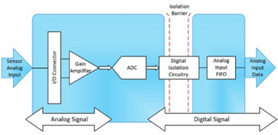
Figure 5: As opposed to analog isolation, digital isolation circuitry is placed after the ADC in the instrument.
Digital isolation can lead to better performance and accuracy, in comparison to analog isolation circuitry, because the measured signal is less altered before it is digitized by the ADC. Digital isolation circuitry also has advantages over analog isolation circuitry because it is typically lower in overall cost and it performs at higher data transfer speeds. However, because digital isolation circuitry is after the ADC, the ADC is more susceptible to the damage a voltage spike can cause.
Isolation Types
We have talked about common isolation topologies for instruments and where the isolation can be applied to the signal within the instrument, but we have not talked about the isolation barrier itself or how the signal crosses the isolation barrier. In this section we will quickly cover the isolation barrier and then we will move into three common isolation types, which use different techniques to transmit the signal data across the isolation barrier.
Physical isolation is the most basic form of isolation, meaning that there is a physical barrier between two electrical systems. This can be in the form of insulation, an air gap, or any nonconductive path between two electrical systems. With pure physical isolation, you can imply that no signal transfer exists between electrical systems. When dealing with isolated measurement systems, the signal of interest needs to cross the isolation barrier with the benefits of removing ground loops. Therefore, you must have a transfer, or coupling, of the signal’s energy across the isolation barrier. Three common techniques of transferring the signal across the isolation are discussed below.
Capacitive Isolation
Capacitive isolation, as seen in Figure 6, uses an electrical field as the form of energy to transfer the signal across the isolation barrier. The electric field changes the level of charge on the capacitor. This charge is detected across the isolation barrier and the charge detected is proportional to the level of the measured signal.
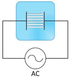
Figure 6: Capacitive isolation uses an electrical field as the form of energy to transfer the signal across the isolation barrier.
Inductive Isolation
Inductive isolation uses a transformer, shown in Figure 7, to transfer a signal across an isolation barrier. The transformer generates an electromagnetic field, proportional to the measured signal, as the form of energy to cross the isolation barrier.
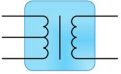
Figure 7: Inductive isolation uses a transformer, notated with the above symbol, to transfer a signal across an isolation barrier.
As in capacitive coupling, inductive isolation can provide relatively high-speed data transmission rates. In addition to high-speed transmission, inductive coupling uses low power for the data transmission. However, inductive coupling is susceptible to interference from surrounding magnetic fields because it uses electromagnetic fields as the method to cross the isolation barrier. If external magnetic fields do interfere with the electromagnetic field produced by the transformer, this could affect the accuracy of the measurement.
Optical Isolation
Optical isolation uses an LED and a photodetector to transmit the signal information across the isolation barrier. The isolation barrier in optical isolation is typically an air gap and the signal is transmitted using light. The light intensity produced by the LED is proportional to the measured signal.
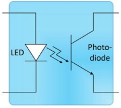
Figure 8: Optical isolation uses an LED and a photodetector to transmit the signal information across the isolation barrier.
Because optical isolation uses light as the energy to transfer the measured signal across the isolation barrier, it gains the advantage of immunity from electrical- and magnetic-field interference. This can make optical isolation an effective technique in industrial areas where strong electric or magnetic fields could be present. The advantages gained by using light are balanced by some disadvantages. Optical isolation typically has slower data transfer rates, which are limited to the LED switching speed. It also has relatively high power dissipation when compared to capacitive and inductive isolation.
Summary
- Isolation is a method of physically and electrically separating two distinct parts of an instrument.
- Breaking ground loops to measure the signal of interest more accurately is a main advantage of isolated measurement systems.
- Based on the application requirements, you can choose the isolation topology that best fits system needs.
- Channel-to-earth isolation isolates the channels from the instrument ground.
- Bank (channel-to-bus) isolation isolates groups (banks) of lines from other groups of lines as well as from the instrument ground.
- Channel-to-channel isolation isolates every line from every other line present and from the instrument ground.
- Analog isolation circuitry protects the ADC from high voltages and transient voltages, but it can add gain, nonlinear, and offset errors to the signal before it reaches the ADC.
- Digital isolation circuitry does not protect the ADC, and its advantages over analog isolation include lower cost, higher data transmission speeds, and greater accuracy because the signal is less altered prior to reaching the ADC.
- Isolation type overview:
| Isolation Type | Advantages | Disadvantages |
|---|---|---|
Capacitive | • Fast data transmission rate • Magnetic field interference immunity | • Susceptible to electric field interference |
| Inductive | • Fast data transmission rate • Electric field interference immunity | • Susceptible to magnetic field interference |
Optical | • Electric field interference immunity • Magnetic field interference immunity | • Slower data transmission rates • Relatively high power dissipation |
Next Steps
- Learn about NI PXI Instruments for automated characterization, validation, and production test
- Download all instrument fundamentals content