Chassis, Earth and Signal Grounding: Terminology and Symbols
Overview
Contents
Introduction
The use of grounding symbols does not always strictly adhere to industry standards; it can be difficult to understand which ones are used and in what context. Most of the time the ground symbol you are most familiar with, the 3 decreasing-length lines, is the one that is used in a generic sense to illustrate ground.
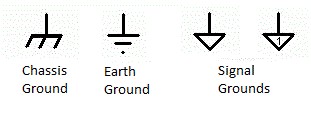
The three diagonal lines and the decreasing horizontal bars represent chassis and earth ground, respectively. Furthermore, the three decreasing-length parallel lines represent analog or circuit ground. The hollow triangle usually means digital ground, but is often used as a reference ground. A letter or number in the triangle may be used to indicate references that are in common with each other.
Note that none of these grounds are necessarily equivalent. Ground is a point of reference from which a potential (voltage) may be measured. Different grounds will have voltages between them that we must take into account when connecting equipment together and making measurements.
Earth ground means that the earth itself is used as a reference point.
Power Line Ground
Power line ground is a safety device. Currents that do not follow their normal path will be directed to earth through an alternate path. In (modern) residential wiring this will be the green or bare copper wire in your power lines. Current normally does NOT flow through this conductor, it is for safety purposes only. Many pieces of equipment will use this wire as a signal reference since it does connect directly to earth at some point and does not normally carry current. However, if there is a fault in the power line wiring, this ground could become a current carrying conductor.
Power line neutral is the return path for the power supplied to you by the power company. It is referenced (connected) to earth at the point at which power is supplied to your building. This is the white wire in your power supply lines. Power is delivered along the black wire, and returned along the white, completing the circuit path. This line is the reference for your power, the black line is at 110 VAC with reference to the white return line.
Chassis Ground
Chassis ground is the metal housing that encases an electrical device. In the event of an electrical short into the chassis, chassis ground is intended to redirect errant current to ground instead of to a person who contacts it. The chassis may be connected to the green ground wire of your power lines. The chassis may or may not be connected to some other line to ground it. The negative side of signal connections may also be connected to the chassis, referencing any signal to the chassis ground. Many devices allow you to choose to connect or disconnect your signals' reference to chassis ground.
National Instruments Hardware
NI data acquisition (DAQ) devices have different grounds that are used depending on the application: Analog Input Ground (AIGND), Analog Output Ground (AOGND), and Digital Ground (DGND). They are all referenced to a single point on the card itself, but they have different ground planes on the card to minimize noise and cross-talk. Digital ground is particularly noisy because of the high frequency content of digital signals. One common point of confusion with National Instruments analog input DAQ devices has to do with AISENSE, the connection used in Non-Referenced Single-Ended (NRSE) measurement mode. AISENSE is a line that makes the reference of all single-ended AI channels common to each other; they all share a common reference. However, it is NOT connected to any ground anywhere else; it is floating with respect to AIGND, AOGND, and DGND.