Pinout of the 9 Pin DIN Cable for the NI-DMM and NI High-Speed Digitizers
Overview
Contents
Introduction
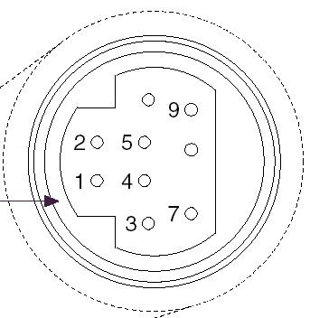
If you look at the connector on the front of the DMM or digitizer you will see a connector similar to the image below. A few pins are not labeled, Pin 6 is above pin 5 and pin 8 is above pin 7.
DMMs
The Digital Multimeter Trigger Cable (p/n 184931-0R5) provides BNC connectivity to pins 6 and 9 via the 9-pin DIN connector on the DMM. Only 3 of the 9 pins are used on the DMM, as listed below.
- Pin 2 - Ground
- Pin 6 - Measurement Complete
- Pin 9 - External Input Trigger
If you need to make a custom cable, use the diagram found on page 3 of the NI 4021 Kit Installation Guide, see related links.
Digitizers
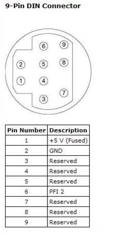
The Aux100 9-Pin DIN to BNC Female Cable (p/n 185259-0R3) provides connectivity to PFI 2 for the older non-Synchronization and Memory Core digitizers (non-SMC) . These digitizers include the NI-5102/5112/5911. A picture of the 9-Pin DIN connector and pin assignments for these devices is shown below.
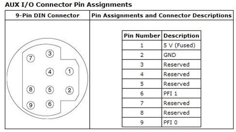
The 9-Pin DIN to 2 BNC Female Cable (p/n 189919-0R5) provides connectivity to PFI 0 and PFI 1 for many of the newer (SMC) digitizers. These digitizers include the NI-5114/5122/5124/5142/5922. A picture of the 9-Pin DIN connector and pin assignments is shown below.